OPERATIVE TECHNIQUE
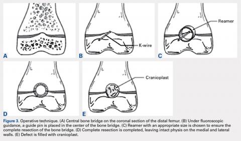
With the patient supine on the operating table and after the administration of general anesthesia, 3-dimensional (3-D) fluoroscopy was used to localize the bone bridge, which confirmed the fluoroscopic location that was previously visualized through preoperative 3-D imaging. The leg was elevated, and a tourniquet was applied and inflated. A lateral parapatellar approach was used to isolate the distal femoral physis anteriorly because the bone bridge was centered just lateral to the central portion of the distal femoral physis. A Kirschner wire was placed in the center of the bridge under anteroposterior and lateral fluoroscopic imaging (Figures 3A-3E).
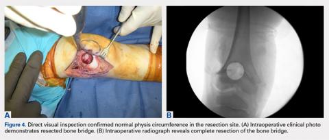
A series of core reamers were then introduced, starting at 10 mm diameter and increasing to 18 mm diameter before complete resection was accomplished. Irrigation was used to prevent the thermal necrosis of the physis during reaming, and lateral fluoroscopic imaging was used to prevent injury to the posterior neurovascular structures. Each time a reaming was completed, the physeal bone bed was inspected to confirm complete bone bridge resection (Figure 3C). Once 18 mm of the physis had been removed, direct visual inspection confirmed normal physis was present on all sides of the bone that remained following physeal bar resection (Figures 3D and 4A, 4B). The defect was irrigated with normal saline and filled with cranioplast (Figure 3E). Cranioplast (the methyl ester of methacrylic acid that easily polymerizes into polymethyl methacrylate) was chosen because the amount of adipose tissue was insufficient for harvesting for interposition given the patient’s lean body habitus. Moreover, the use of the cranioplast prevented the occurrence of exothermic reactions during curing and provided hemostasis because the cranioplast occupied the entire cavity and was strong enough to provide structural support.13 When partially set into a putty-like state to allow molding, the cranioplast was carefully contoured within the femoral trochlea. To protect the resection site from pathologic fracture, the patient was placed in a long-leg cast, and only protected weight-bearing with the use of a walker was allowed for 6 weeks.OUTCOME
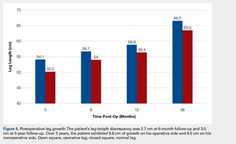
The patient healed uneventfully, and early range-of-motion exercises were started 6 weeks postoperatively. At 6-month follow-up, his leg-length discrepancy was 2.7 cm, and the bone bridge did not recur. At 3-year follow-up, his leg-length discrepancy was 3.0 cm, and the bone bridge did not recur. Over the 3 years postoperatively, the patient exhibited 9.8 cm of growth on his operative side and 9.5 cm on his nonoperative side (Figure 5).
The patient has returned to full function and has had no pain, patellofemoral complaints, or complications associated with the cranioplast. He currently is being followed for his leg-length discrepancy. A contralateral epiphysiodesis is planned to equalize his leg-length discrepancy.DISCUSSION
Given the considerable growth potential of the distal femoral physis,1,14-16 an injury to the distal femoral physis and the formation of a physeal bone bridge can have a profound effect on a young patient in terms of leg-length discrepancy and angular deformity. Fracture from trauma or infection is a common cause of physeal bone bridges.6,17-19 The etiology of our patient’s distal femoral physeal bone bridge is idiopathic, which is considerably less common than other etiologies, and the incidence of idiopathic physeal bone bridge formation is not well established in the literature. Hresko and Kasser21 identified atraumatic physeal bone bridge formations in 7 patients. Among the 13 patients with physeal bone bridges described by Broughton and colleagues,20 the cause of bridge formation is unknown in 1.
Physeal bone bridges that form centrally are particularly challenging because they are difficult to visualize through a peripheral approach. A number of methods for resecting central physeal bone bridges have been described. These methods have varying degrees of success. In 1981, Langenskiöld7 first described the creation of a metaphyseal mirror and the use of a dental mirror for visualization. This technique, however, yielded unfavorable results in 16% of patients. Williamson and Staheli9 reported poor results in 23% of patients. Loraas and Schmale4 described the use of an endoscope, termed an osteoscope, for visualization, citing advantages of superior illumination and potential for image magnification and capture. Marsh and Polzhofer8 also showed this technique to have low morbidity but poor results in 13% of patients, whereas Moreta and colleagues10 reported poor results in 2 out of 5 patients. The rate of poor results of these methods may be related to the technical difficulty of using dental mirrors and arthroscopes and can be improved by highly efficient direct methods with improved visualization, such as the method described in this article.
Continue to: Proper imaging is necessary for...


